 ×
MOTHCO · FIELD MANUAL
HD VIDEO TAP
FOR ARRI 435 →
MOTHCO
MCO-435.
A modern, compact tap with a full OSD menu. Replaces the analog video assist on the ARRIFLEX 435 with an HD-SDI 1080p output. This manual covers installation, the two settings that matter at startup, and how to walk out of the most common on-set symptoms.
One Sony sensor,
one HD-SDI connector.
2 MP 1/2.8" Sony IMX CMOS sensor, progressive HD-SDI output at 24/25/30 fps, regulated Lemo 2-pin power. Machined aluminum body — 58 × 52 × 52 mm, 365 g.
Sensor
Sony IMX CMOS, 1920 × 1080 effective pixels. HD 16:9 format, progressive scan. Internal sync.
Output
Single BNC HD-SDI. The EX-SDI modes (1.0 / 2.0) exist in the menu but aren't used in the LENSO flow — always force HD-SDI for compatibility with the rest of video village.
Power
Regulated DC, reverse-polarity protected. Pin 1 (red dot) = GND, Pin 2 = +DC. Operating range 10-50 °C, humidity 20-80 %.
THREE M4 SCREWS.
CAMERA OFF.
The tap mounts to the ARRI 435 body with three M4 hex-socket screws. The whole operation happens with the camera powered down and with no power at the tap. Tighten the three screws evenly in a crosswise pattern so no side sits unevenly against the camera body.
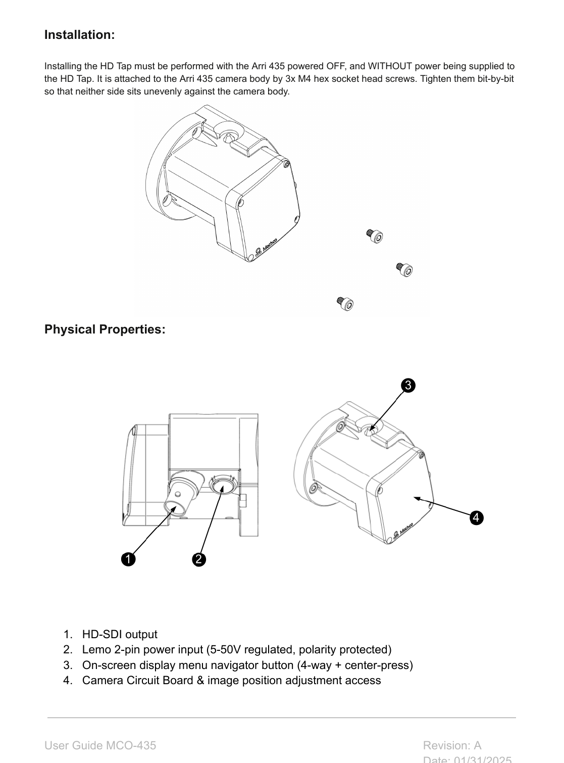
Connectors — identify each one
- ① HD-SDI output
- BNC. Direct to monitor or to the wireless TX.
- ② Power
- Lemo 2-pin. 12–36 V DC regulated.
- ③ OSD navigator
- 4-way joystick with center press. Only control for the whole menu.
- ④ PCB access
- Access to the circuit board for image position adjustment.
Image position adjustment
The sensor PCB is held by four M2 screws damped by rubber washers. Loosening or tightening crosswise pairs tilts the sensor plane to center the image inside the optical viewfinder frame.
It's a delicate adjustment — only touch it if the viewfinder center doesn't coincide with the tap center. Tighten each screw gently to avoid crushing the washer.
Two hard rules from the manufacturer
Beware of hot plugging. Connect monitors, TX, or accessories with everything off. Power up the tap first and the monitor second.
Beware of voltage differential. If the monitor runs off a very different power source than the tap (typical on steadicam), daisy-chain HD-SDI from tap → wireless TX → monitor. A large ground differential can trip the tap's protection or damage the circuit.
Lemo 2-pin.
Red dot to GND.
Regulated DC between 12 V and 36 V. Pin 1 (red-dot mark) is GND, pin 2 is +DC. The connector is polarity-protected, but don't push your luck: wire it right.
Lemo 2-pin pin-out
- Pin 1 · red dot
GND- Pin 2
+DC · 12–36 V
Where it comes from
The cameras we ship carry a Lemo 2-pin to D-tap cable from the camera battery. For shoots with two village monitors hanging off the same chassis, consider a dedicated power line — keep the tap isolated from the voltage drops a TX creates when it powers up.
TWO MENU LINES
BEFORE THE FIRST SHOT.
Before you start rolling, confirm the menu boots with these two values. These are the only "must-do" settings — the rest can stay at factory defaults.
SYSTEM · frame rate and region
Open the menu (center press on the navigator) → 7. SYSTEM → FRAME RATE. Set:
- 1080/24 if shooting with TV SYSTEM
US(NTSC)(60 Hz). - 1080/25 if shooting with TV SYSTEM
EU(PAL)(50 Hz). - To move from 25p to 30p, change TV SYSTEM first — the menu won't offer 30p while PAL is set.
EXPOSURE · manual shutter at 1/30
Open 2. EXPOSURE → SHUTTER → MANUAL → 1/30. Two reasons:
- In
AUTO, the shutter moves constantly to compensate for light — producing visible flicker on the monitor. FLICKERLESScorrects for mains frequency (TV at 50 Hz in a PAL room), but not for the 435's own mirror-shutter flicker. For a clean viewfinder: always manual at 1/30.
When leaving the menu — SAVE, not CANCEL
Item 8. EXIT has two options. SAVE stores the settings and exits the menu; CANCEL exits without saving. Confuse the two and the next boot returns to factory defaults.
Eight items,
one joystick.
The physical navigator (4-way button with center press) is the only control. Up/down moves between items, left/right changes the value, press enters a submenu marked with ↵. The root menu has eight entries.
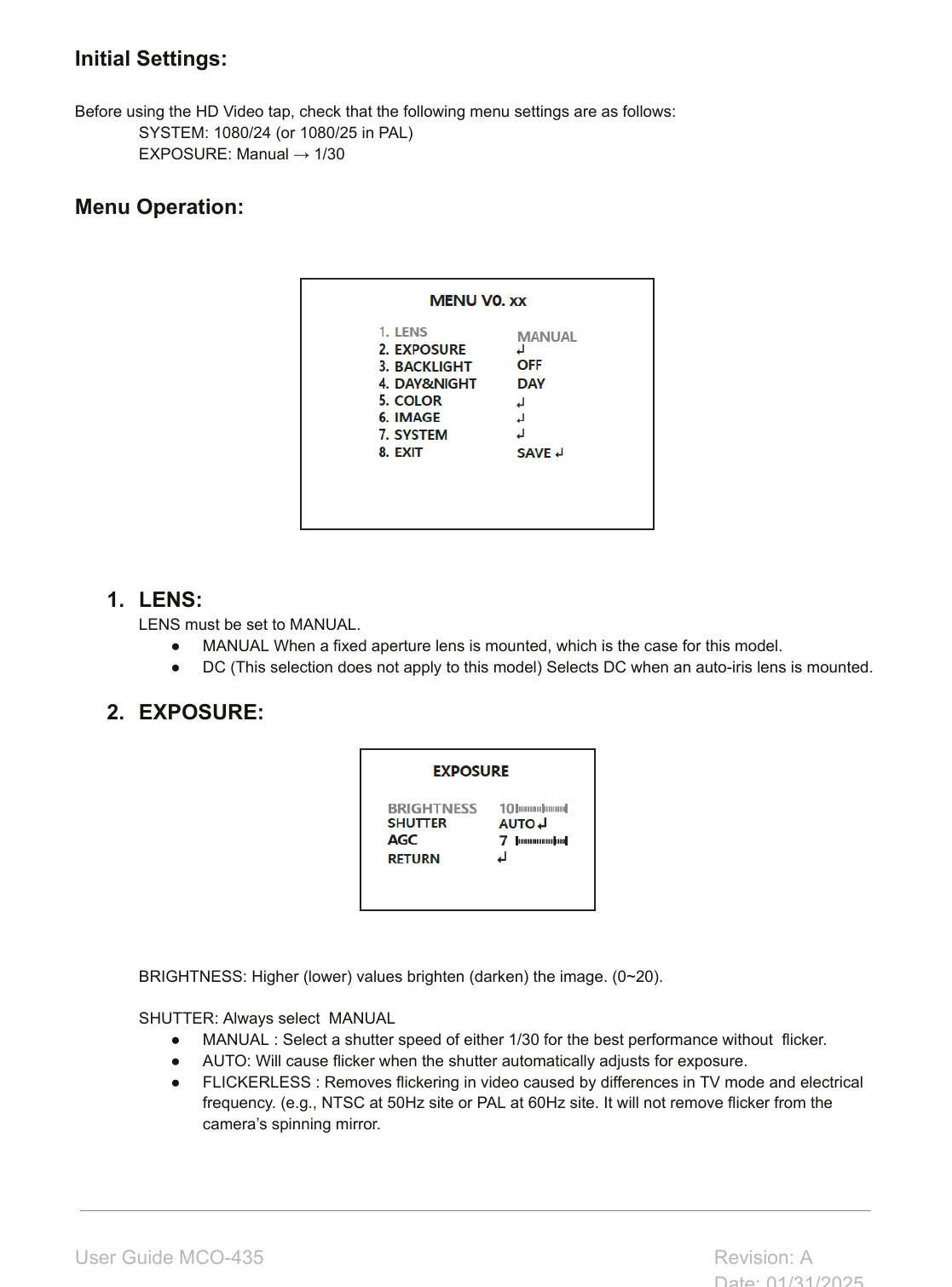
1 · LENS
Always MANUAL. The MCO-435 ships with a fixed-aperture integrated lens; the DC value is for auto-iris (doesn't apply).
2 · EXPOSURE
Brightness, shutter, sens-up, and AGC. The submenu most touched on set — see section 07.
3 · BACKLIGHT
Backlight compensation: HLC (mask blown zones), BLC (expose a defined rectangle), or HDR (CLEAR or DOL).
4 · DAY & NIGHT
Force color (DAY), b/w (NIGHT), or let the sensor decide by light (AUTO). Normal shoot: DAY, always.
5 · COLOR
White balance and color gain — see section 08.
6 · IMAGE
Sharpness, gamma, mirror/flip, D-WDR, defog, shading, privacy masks — see section 09.
7 · SYSTEM
Output (HD-SDI), frame rate, TV region (US/EU), language, cam title, RS-485 comm, factory reset — see section 10.
8 · EXIT
SAVE saves and exits. CANCEL exits without saving. Any change made in the other 7 items is lost if you hit CANCEL by mistake.
Brightness, shutter, AGC.
The four variables under the EXPOSURE submenu. In standard LENSO flow, SHUTTER is always manual at 1/30 — the rest can stay at defaults.
Controls
- BRIGHTNESS
- 0-20. Up to brighten, down to darken. Default
10. - SHUTTER
- MANUAL 1/30 always. AUTO generates flicker. FLICKERLESS helps with mains but not with the 435 mirror.
- SENS-UP
- Low-light exposure multiplier (×2, ×4…). Leave
OFFunless extreme night work. - AGC
- Max allowed gain. Higher = more noise. Default
7is usually fine.
Symptom → tweak
- Continuous flicker
- SHUTTER to
MANUAL 1/30. - Dark image
- Raise BRIGHTNESS first; if that's not enough, raise AGC.
- Visible noise
- Lower AGC. If the shot still needs more light, open the lens aperture.
- Blown background
- BACKLIGHT →
HLCorBLCin the root menu.
AUTO or PRESET —
rarely MANUAL.
The COLOR submenu has two items: WHITE BAL and COLOR GAIN. In practice, the AC leaves it on AUTO or PRESET and touches COLOR GAIN if the village wants more or less saturation.
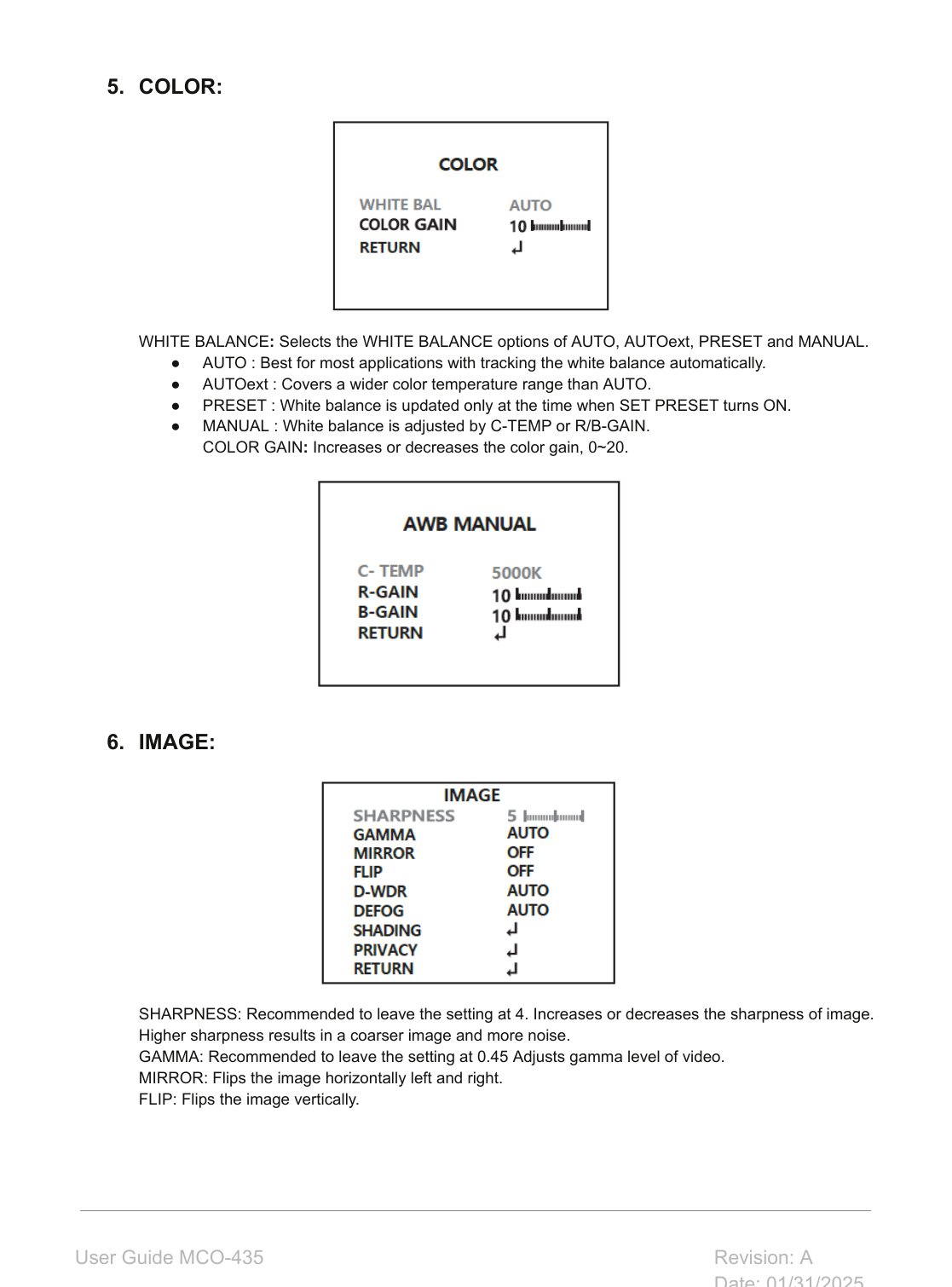
- AUTO
- The sensor tracks white continuously. Good for most setups under stable light.
- AUTOext
- Wider color-temperature range than
AUTO. Useful when mixing tungsten interior with HMI exterior. - PRESET
- Fixed white — locked in by pressing SET on a white reference card. Doesn't follow light changes.
- MANUAL
- Enters the AWB MANUAL submenu: C-TEMP (3000K, 5000K, 8000K), R-GAIN and B-GAIN (0-20). Only if the DP wants a specific look.
- COLOR GAIN
- 0-20. Up to saturate, down to desaturate. Default
10.
Sharpness, gamma, flip,
privacy masks.
The IMAGE submenu groups eight processing settings. Factory recommendation is to leave most at defaults; only MIRROR/FLIP and PRIVACY masks get touched on real shoots.
Recommended parameters
- SHARPNESS
- Default
4. Higher = harder image and more noise. - GAMMA
- Default
0.45. Standard curve for HD-SDI. - MIRROR
- Horizontal flip.
OFFby default. - FLIP
- Vertical flip.
OFFby default. Useful if the tap mounts inverted on steadicam.
Compensation and masks
- D-WDR
- Compensates dark areas in high-contrast scenes. Leave on
AUTO. - DEFOG
- Improves visibility through haze.
AUTO,MANUAL, orOFF. - SHADING
- Compensates corner fall-off.
- PRIVACY
- Up to 16 rectangular masks (programmable size, color, position, transparency). Useful to cover a logo or a serial number in the background.
Output, frame rate, region.
The SYSTEM submenu controls output format and global preferences. Two things to always check; the rest is optional.
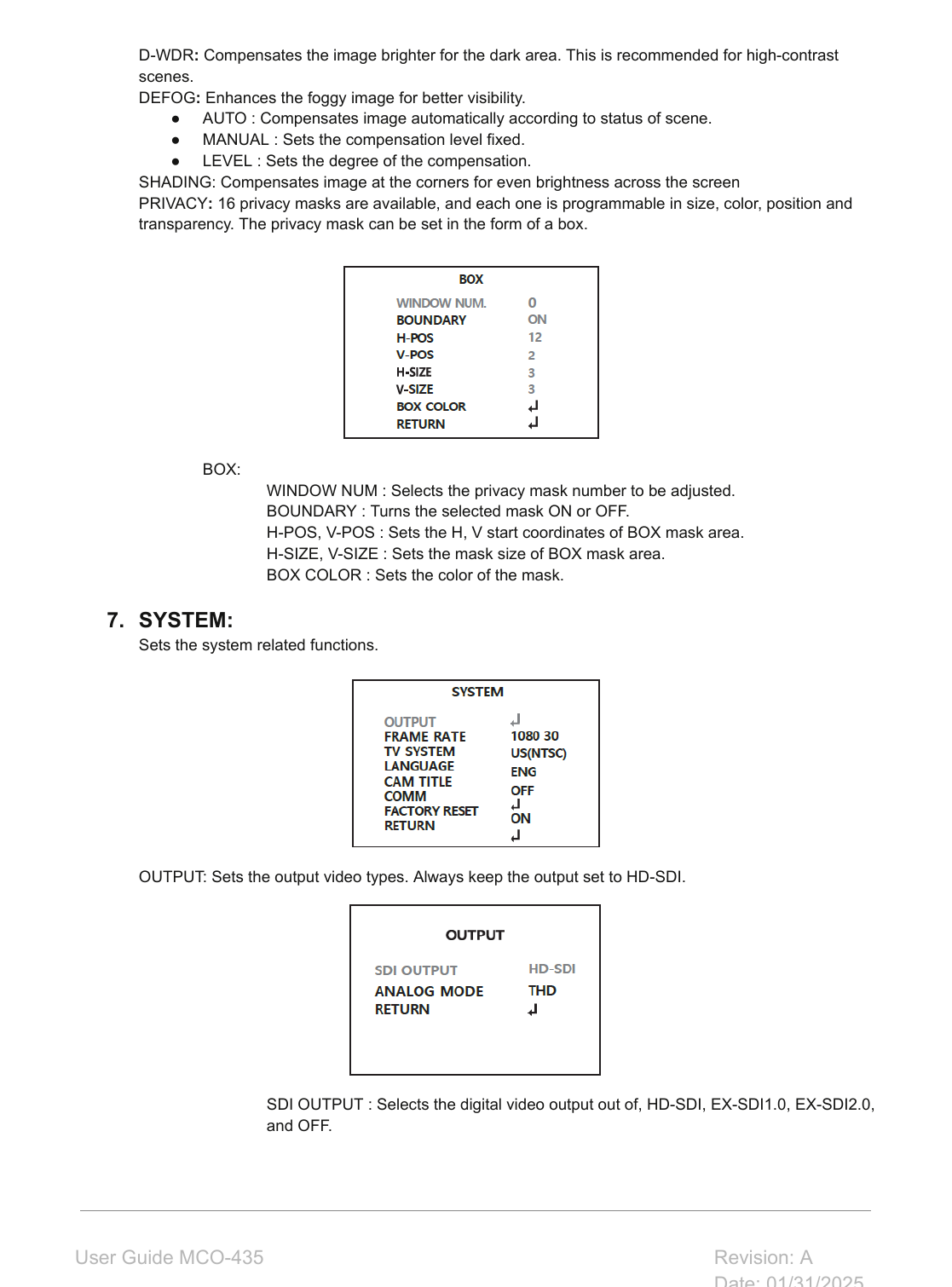
Required
- SDI OUTPUT
- Always
HD-SDI. TheEX-SDI 1.0/2.0andOFFoptions aren't used in LENSO flow. - ANALOG MODE
- Don't switch to
ANALOG. Leave it as it comes from factory (THD). - FRAME RATE
- 1080 24p, 25p, 30p, 60p, 50p; 720 60p or 30p. For 25p, set TV SYSTEM to PAL first.
- TV SYSTEM
US(NTSC)for 60 Hz regions,EU(PAL)for 50 Hz.
Optional
- LANGUAGE
- English, Korean, Japanese, Chinese (simplified and traditional), German.
- CAM TITLE
- Up to 8 alphanumeric characters overlaid on the image. Position OFF / RIGHT UP / LEFT DOWN.
- COMM
- Camera ID and RS-485 speed (default
ID:1,9600 BPS). Only if a control board is present. - FACTORY RESET
- Returns everything to factory. Afterwards redo the two initial settings.
Fast on-set triage.
The most common symptoms and the shortest fix for each. Power, shutter, and output cover 90 % of the calls.
| Symptom | Probable cause | Fix |
|---|---|---|
| No signal on the monitor | BNC not seated, or a "non-SDI" cable (an analog-only PAL/NTSC cable). | Reseat the BNC. Try a short SDI reference cable. An analog PAL/NTSC cable will fail even at short SDI distances. |
| Flicker in the image | SHUTTER on AUTO or FLICKERLESS. |
Menu → 2. EXPOSURE → SHUTTER → MANUAL → 1/30. |
| Image off-center in the viewfinder | Mechanical alignment of the sensor against the optical axis. | Open the PCB access (screw ③) and tweak the four M2 screws in cross pattern, see section 03. Don't do it on set — better bring it to the warehouse. |
| Random image dropouts | Voltage drop below 12 V or ground differential with the monitor. | Swap the camera battery, verify the monitor is daisy-chained through the wireless TX (not direct to the tap). |
| Over-saturated or flat colors | COLOR GAIN out of range or AWB on the wrong mode. | Menu → 5. COLOR → WHITE BAL AUTO, COLOR GAIN 10. If the DP wants a look, use AWB MANUAL with fixed C-TEMP. |
| Image inverted | FLIP and/or MIRROR active — typical when inheriting settings from an earlier steadicam build. | Menu → 6. IMAGE → MIRROR OFF, FLIP OFF. |
| Settings lost on power-off | Exited the menu with CANCEL instead of SAVE. |
Back to the menu, redo the changes, exit via 8. EXIT → SAVE. |
| Artifacts after hot-plugging an accessory | Hot-plug with the tap powered. | Cut tap power, connect the accessory, power on again. Protection should have caught it — but it's not free. |
| Nothing works after too many menu changes | Menu in inconsistent state. | Menu → 7. SYSTEM → FACTORY RESET → ON. Then redo the two initial settings (SYSTEM and SHUTTER). |